
VIP member

YU-1A corrosion-resistant submersible pump
One Product Introduction: The YU-1A series portable submersible pump is an improved version of the YU-1 model. Its flow-through components are both mo
Product details
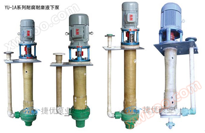
One Product Introduction
The YU-1A series portable submersible pump is an improved version of the YU-1 model, with flow components made of both ultra-high molecular weight polyethylene (UHMWPE) integral molding and reinforced polypropylene integral injection molding. It has excellent corrosion and wear resistance and is suitable for transporting acidic or alkaline slurries or clear liquids in the temperature range of -20 ℃ to 80 ℃. The obvious difference between this pump and the YU-1 pump is the addition of a coupling between the motor shaft and the pump shaft, which enhances the stability of the pump head operation and provides convenience for users' maintenance.
This series of pumps has been mass-produced for over ten years and has been used by more than 3000 users and 8000 positions. Its temperature resistance, corrosion resistance, mechanical stability, wear resistance, and economic efficiency in operation have been recognized by users. Therefore, this product is a stable, technologically mature, popular, and standardized anti-corrosion pump product, known as the "old scholar" variety by old users.
This series of pumps can be widely used in the following industries:
(1) Non ferrous metal wet smelting industry: particularly suitable for the transportation of various acid liquids, alkali liquids, corrosive slurries, electrolytes, waste acids, sewage and other media in wet smelting of lead, zinc, gold, silver, copper, manganese, cobalt, rare earth and other materials.
(2) Sulfuric acid phosphate fertilizer industry: transportation of dilute acid, mother liquor, fluorosilicic acid containing silica gel, phosphoric acid slurry and other media.
(3) Water treatment and environmental protection industry: capable of transporting various types of wastewater with impurities.
(4) Pesticides, dyes, and fine chemical industries: can transport clear liquids or slurries containing dilute acids, alkaline liquids, and mixed acids.
(5) The suction and delivery of corrosive and non corrosive clear liquids or slurries in other industrial production processes.
The YU-1A-J series corrosion-resistant and wear-resistant submersible pump is equipped with a stirring blade at the lower part of the YU-1A series submersible pump, which can stir the sediment under the liquid while transporting it. Suitable for cleaning and transporting sediment materials in tanks and containers such as slurry or sewage tanks, sedimentation tanks, etc. containing solid materials.
II Model meaning

III Performance characteristics of the pump
3.1 The pump body is molded as a whole, and the connecting cylinder is made of fiberglass, which has excellent anti-corrosion performance and steel strength. Therefore, the stability and reliability of the pump body operation are excellent. The overcurrent components are all made of non-metallic materials, with excellent anti-corrosion performance.
3.2 The connection between the pump body and the connecting cylinder, as well as the connection between the pump body and the pump cover, are all connected by large pitch threads, making installation and maintenance more convenient. Due to the absence of metal fastening screws in the underwater area, there is no concern of corrosive damage, and its overall anti-corrosion performance is very superior.
4 Special selection service
There are three common types of submersible pumps with a depth of 0.6 meters, 0.8 meters, and 1 meter. If there are special depth requirements, please specify them when placing an order.
4.2 The installation plate of the submersible pump is marked as square in this manual. If the user has other requirements, it can be made into a circular or other shaped installation plate according to their needs.
4.3 If the user encounters positions with high requirements for transporting large particles and abrasion, please explain. Our factory can assist in selecting impellers and pump covers made of special wear-resistant materials, such as polyurethane and alloy steel.
4.4 In the user's operating conditions, if encountering fluorine-containing media such as hydrofluoric acid, it should be explained so that our factory can select a hydrofluoric acid resistant connecting cylinder for you.
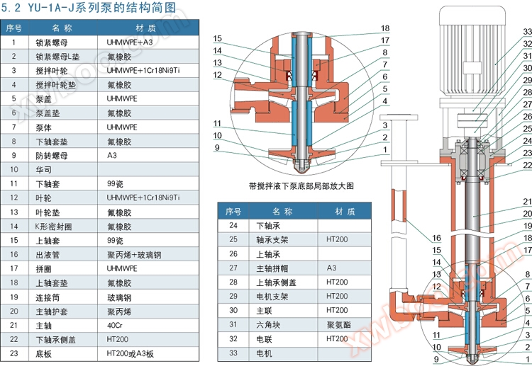
Five Schematic diagram of pump structure
|
serial number
|
Pump Model
|
traffic(m3/h)
|
head(m)
|
speed(r/min)
|
Motor power(kw)
|
Total weight(kg)
|
remark
|
drawing
|
|
1
|
25YU-1A-3-5
|
3
|
5
|
2900
|
0.75
|
55
|
Underwater depth less than 1m
|
 1.rar 1.rar
|
|
2
|
25YU-1A-3-10
|
3
|
10
|
2900
|
1.1
|
55
|
||
|
3
|
25YU-1A-5-15
|
5
|
15
|
2900
|
1.1
|
55
|
||
|
4
|
25YU-1A-5-20
|
5
|
20
|
2900
|
1.1
|
55
|
||
|
5
|
25YU-1A-5-20
|
5
|
20
|
2900
|
1.5
|
55
|
2.rar
|
|
|
6
|
32YU-1A-5-25
|
5
|
25
|
2900
|
2.2
|
63
|
3.rar
|
|
|
7
|
32YU-1A-10-10
|
10
|
10
|
2900
|
1.5
|
63
|
||
|
8
|
32YU-1A-10-15
|
10
|
15
|
2900
|
1.5
|
63
|
||
|
9
|
32YU-1A-15-15
|
15
|
15
|
2900
|
2.2
|
63
|
||
|
10
|
32YU-1A-10-20
|
10
|
20
|
2900
|
2.2
|
63
|
||
|
11
|
40YU-1A-10-30
|
10
|
30
|
2900
|
3
|
95
|
4.rar
|
|
|
12
|
40YU-1A-15-20
|
15
|
20
|
2900
|
3
|
95
|
||
|
13
|
40YU-1A-15-28
|
15
|
28
|
2900
|
3
|
95
|
||
|
14
|
40YU-1A-20-10
|
20
|
10
|
2900
|
3
|
95
|
||
|
15
|
40YU-1A-20-20
|
20
|
20
|
2900
|
4
|
108
|
5.rar
|
|
|
16
|
40YU-1A-20-25
|
20
|
25
|
2900
|
4
|
108
|
||
|
17
|
40YU-1A-30-15
|
30
|
15
|
2900
|
4
|
108
|
||
|
18
|
40YU-1A-20-30
|
20
|
30
|
2900
|
5.5
|
126
|
6.rar
|
|
|
19
|
50YU-1A-30-15
|
30
|
15
|
2900
|
5.5
|
126
|
7.rar
|
|
|
20
|
50YU-1A-30-20
|
30
|
20
|
2900
|
5.5
|
130
|
||
|
21
|
50YU-1A-30-25
|
30
|
25
|
2900
|
5.5
|
130
|
||
|
22
|
50YU-1A-30-30
|
30
|
30
|
2900
|
7.5
|
130
|
||
|
23
|
50YU-1A-40-10
|
40
|
10
|
2900
|
5.5
|
130
|
||
|
24
|
50YU-1A-40-15
|
40
|
15
|
2900
|
5.5
|
130
|
||
|
25
|
65YU-1A-40-15
|
40
|
15
|
2900
|
5.5
|
165
|
8.rar
|
|
|
26
|
65YU-1A-40-20
|
40
|
20
|
2900
|
7.5
|
170
|
9.rar
|
|
|
27
|
65YU-1A-45-25
|
45
|
25
|
2900
|
7.5
|
170
|
||
|
28
|
65YU-1A-50-8
|
50
|
8
|
2900
|
7.5
|
170
|
||
|
29
|
65YU-1A-45-30
|
45
|
30
|
2900
|
11
|
219
|
10.rar
|
|
|
30
|
65YU-1A-50-25
|
50
|
25
|
2900
|
11
|
219
|
||
|
31
|
65YU-1A-60-20
|
60
|
20
|
2900
|
11
|
219
|
||
|
32
|
80YU-1A-60-30
|
60
|
30
|
2900
|
15
|
280
|
11.rar
|
|
|
33
|
80YU-1A-80-30
|
80
|
30
|
2900
|
18.5
|
310
|
12.rar
|
|
|
34
|
80YU-1A-100-30
|
100
|
30
|
2900
|
22
|
350
|
13.rar
|
|
|
35
|
100YU-1A-100-26
|
100
|
26
|
2900
|
22
|
450
|
||
|
36
|
100YU-1A-90-30
|
90
|
30
|
2900
|
22
|
450
|
||
|
37
|
100YU-1A-120-25
|
120
|
25
|
2900
|
22
|
450
|
||
|
38
|
100YU-1A-130-23
|
130
|
23
|
2900
|
22
|
450
|
Note: 1 The performance parameters of YU-1A-J are the same as YU-1A.
2. The parameters mentioned in the table were obtained through experiments with clean water. If conveying other types of media, the motor power varies with the specific gravity of the media. Welcome to call for consultation.
7 Outline drawing and installation dimension table of pump
7.1 Outline drawing of pump

|
serial number
|
Specifications
|
Motor power(kw)
|
Export flange size(mm)
|
Overall dimensions(mm)
|
Insertion port size(mm×mm)
|
Installation board size(mm)
|
drawing
|
|||||||||||||
|
D1
|
D2
|
D3
|
n1-d1
|
H1
|
H2
|
H3
|
H4
|
a1
|
a2
|
a3
|
a4
|
a5
|
b1
|
b2
|
n2-d2
|
|||||
|
1~4
|
25YU-1A
|
0.75~1.1KW-2
|
25
|
85
|
115
|
4-Φ14
|
770
|
930
|
1416
|
150
|
395×220
|
50
|
300
|
70
|
225
|
400
|
250
|
300
|
4-Φ12
|
1.rar
|
|
5
|
25YU-1A
|
1.5KW-2
|
25
|
85
|
115
|
4-Φ14
|
770
|
930
|
1416
|
150
|
395×220
|
50
|
300
|
70
|
225
|
400
|
250
|
300
|
4-Φ12
|
2.rar
|
|
6~10
|
32YU-1A
|
1.5~2.2KW-2
|
32
|
100
|
140
|
4-Φ18
|
770
|
930
|
1416
|
150
|
395×220
|
50
|
300
|
70
|
225
|
400
|
250
|
300
|
4-Φ12
|
3.rar
|
|
11~14
|
40YU-1A
|
3KW-2
|
40
|
110
|
150
|
4-Φ18
|
805
|
980
|
1605
|
150
|
430×250
|
50
|
370
|
100
|
270
|
470
|
300
|
350
|
4-Φ14
|
4.rar
|
|
15~17
|
40YU-1A
|
4KW-2
|
40
|
110
|
150
|
4-Φ18
|
805
|
980
|
1605
|
150
|
430×250
|
50
|
370
|
100
|
270
|
470
|
300
|
350
|
4-Φ14
|
5.rar
|
|
18
|
40YU-1A
|
5.5KW-2
|
40
|
110
|
150
|
4-Φ18
|
805
|
980
|
1605
|
150
|
430×250
|
50
|
370
|
100
|
260
|
470
|
350
|
400
|
4-Φ14
|
6.rar
|
|
19
|
50YU-1A
|
5.5KW-2
|
50
|
125
|
165
|
4-Φ18
|
805
|
980
|
1605
|
150
|
430×250
|
50
|
370
|
100
|
270
|
470
|
350
|
400
|
4-Φ14
|
7.rar
|
|
20~24
|
50YU-1A
|
5.5~7.5KW-2
|
50
|
125
|
165
|
4-Φ18
|
800
|
1000
|
1930
|
150
|
550×315
|
50
|
450
|
100
|
325
|
550
|
350
|
400
|
4-Φ18
|
8.rar
|
|
25~28
|
65YU-1A
|
5.5~7.5KW-2
|
65
|
145
|
185
|
4-Φ18
|
800
|
1000
|
2030
|
150
|
550×315
|
50
|
450
|
100
|
325
|
550
|
350
|
400
|
4-Φ18
|
9.rar
|
|
29~31
|
65YU-1A
|
11KW-2
|
65
|
145
|
185
|
4-Φ18
|
800
|
1000
|
2030
|
150
|
550×315
|
50
|
500
|
150
|
335
|
600
|
400
|
450
|
4-Φ18
|
10.rar
|
|
32
|
80YU-1A
|
15KW-2
|
80
|
160
|
200
|
8-Φ18
|
800
|
1000
|
2030
|
150
|
590×315
|
50
|
500
|
150
|
335
|
600
|
400
|
450
|
4-Φ18
|
11.rar
|
|
33
|
80YU-1A
|
18.5KW-2
|
80
|
160
|
200
|
8-Φ18
|
800
|
1000
|
2030
|
150
|
590×315
|
50
|
500
|
150
|
335
|
600
|
400
|
450
|
4-Φ18
|
12.rar
|
|
34
|
80YU-1A
|
22KW-2
|
80
|
160
|
200
|
8-Φ18
|
800
|
1000
|
2030
|
150
|
590×315
|
50
|
500
|
150
|
335
|
600
|
400
|
450
|
4-Φ18
|
13.rar
|
|
35~38
|
100YU-1A
|
22KW-2
|
100
|
180
|
220
|
8-Φ18
|
815
|
1035
|
2045
|
150
|
590×365
|
50
|
540
|
170
|
345
|
640
|
440
|
500
|
6-Φ18
|
|
Note: 1 The installation dimension chart of YU-1A-J series pumps is provided to customers during ordering.
2. The size of the insertion port is the maximum physical external dimension of the pump below the installation plate.
3. The installation size is 1 meter underwater depth. If the underwater depth H1 is 0.6 or 0.8, except for H2, H3, and H1, the other dimensions remain unchanged.
4. Our company reserves the right to make technical improvements and size corrections without notifying users.
8 Installation, use and maintenance instructions
8.1 Installation and Inspection
Fix the pump vertically in the desired position and connect the outlet pipeline. After installation, manually rotate the coupling to see if it operates flexibly. If it does not rotate flexibly or has abnormal noise, jamming or other abnormalities, the pump should be disassembled again for inspection, foreign objects should be cleaned, noise should be eliminated, or the gap between the impeller and the pump body can be adjusted by adding or removing impeller pads. This gap should be ensured to be between 1-2mm. Adjust the gap between the impeller and the pump cover by adding or removing pump cover pads. This gap should be ensured to be between 1-2mm. After installation, rotate the coupling again and repeat this process until it rotates flexibly before connecting the power. Follow the startup program to put the pump into operation.
8.2 Startup
Connect the power point to start and check if the direction of motor rotation is consistent with the direction indicated by the arrow on the pump. If not, reconnect and adjust the wiring; After the motor is running normally, the outlet valve should be slowly opened to the desired working state.
8.3 Parking
Close the outlet valve first, then turn off the power.
8.4 Disassembly and assembly sequence (refer to the structural diagram of the pump)
▲ Disassembly sequence of YU-1A series pump:
a. First, remove the liquid outlet pipe 12;
b. Unscrew filter cover 1 (right-hand thread), unscrew pump cover 2, and remove pump cover gasket 3;
c. Unscrew the locking nut 5 and anti rotation nut 7, and then remove the locking nut pad 6, Huasi 8, impeller 9, impeller pad 10, and shaft sleeve 11 accordingly;
d. Unscrew pump body 4 (right-hand thread), unscrew fitting ring 14 (left-hand thread), and remove K-shaped sealing ring 13.
▲ Disassembly sequence of YU-1A-J series pumps:
a. First, remove the liquid outlet pipe 16;
b. Unscrew the locking nut 1 and anti rotation nut 9, and then remove the locking nut pad 2, Huasi 10, mixing impeller 3, mixing impeller pad 4, lower shaft sleeve 11, and lower shaft sleeve pad 8 accordingly;
c. Unscrew pump cover 5, remove pump cover gasket 6, remove impeller 12, impeller gasket 13, and upper shaft sleeve 15;
d. Unscrew pump body 7 (right-hand thread), unscrew fitting ring 17 (left-hand thread), and remove K-shaped sealing ring 14.
The installation sequence is opposite to the disassembly sequence, and special attention should be paid to the installation of gaskets in each part.
8.5 Precautions
Due to the fact that most of the parts of the pump are made of plastic, it cannot be subjected to strong impact and twisting to avoid unnecessary damage.
8.6 Special installation tips

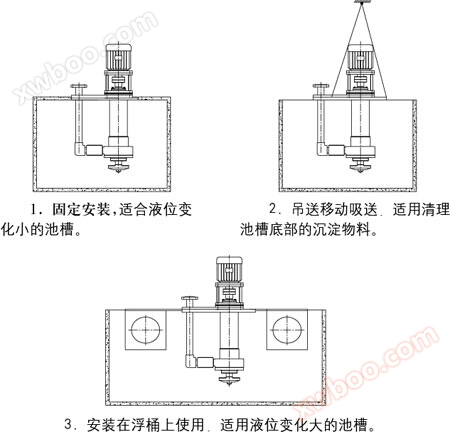
Please note: The distance between the highest liquid level and the pump bottom plate should be greater than 250mm to prevent liquid from corroding the bearings.
8.7 YU-1A-J series pump installation diagram and instructions
Online inquiry
-
Contacts
-
Company
-
Telephone
-
Email
-
WeChat
-
Verification Code
-
Message Content
-