
VIP member

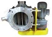
Rotating feeding valve (closing fan)
Product Overview: Rotary Feeding Valve (Shutoff Fan) Product Description: In pneumatic conveying devices, rotary valves are commonly used to unload ma
Product details
Rotating feeding valve (closing fan)
Product Description
In pneumatic conveying devices, rotary valves are often used to unload materials and dust, and to block external air from entering the pneumatic conveying system during the unloading process. At present, there are several types of rotary discharge valves, including impeller type and valve type.
1、 Wheel type unloader
1. Basic characteristics: The impeller type unloader is a commonly used discharge equipment in pneumatic conveying systems, and it is used as a feeder in medium and low-pressure pressure feeding systems. In the powder processing, it is widely used, not only for feeding and unloading, but also for measuring and batching.
The impeller unloader has a reasonable structure, reliable operation, small volume, and scientific manufacturing. It consists of a rotating impeller with a grid chamber and a fixed shell, suitable for discharging powdery and small block materials with good flowability and low grindability.
When the impeller is driven by the transmission mechanism to rotate inside the housing, the granular material falling from the upper separator (or hopper) enters the impeller compartment through the feed port and is sent to the discharge port for discharge along with the rotation of the impeller. Throughout the entire working process, this type of unloader is capable of continuously and quantitatively feeding and unloading materials. Due to the tight fit between the impeller and the shell, it has a certain degree of airtightness, which can reduce air leakage during the unloading process. Therefore, in pneumatic conveying systems, it is also known as a closing fan, locking valve, etc.
2. The structural form of the impeller unloader varies depending on the characteristics and purposes of the discharged materials.
1) According to the arrangement of the transmission shaft, it can be divided into two types: horizontal shaft unloaders and vertical shaft unloaders. The former is widely used in powder engineering and pneumatic conveying systems, while the latter is only used to discharge fine-grained materials from the silo for batching, with high manufacturing and management costs for the horizontal axis type.
2) From the perspective of the basic structure of impellers, they can be divided into two types: impellers with side baffles and impellers without side baffles. The former discharges granular materials without direct contact with the outer shell end cover, but due to the possibility of dust leaking into the cavity between the side baffle and the outer shell end cover, it may sometimes affect the rotation of the impeller; The latter has a simpler structure, but the end cap is prone to wear when transporting abrasive materials.
3) Considering the requirements for good sealing performance, the impeller unloader has different structural characteristics. During operation, it can ensure that the blades are tightly attached to the inner wall of the shell to reduce air leakage.
4) In order to prevent the impeller from getting stuck by debris during the operation of the unloader, some anti jamming measures have been taken in the structure of the unloader. When the impeller is stuck by foreign objects, the moving part of the shell can automatically move outward to make way for the passage, allowing the foreign objects to be removed. Its structural characteristics are: according to the requirements of sealing and wear resistance, the blade end is equipped with adjustable wear-resistant rubber strips; According to the anti jamming requirements, the feeding port adopts a structure inclined towards the direction of rotation and is equipped with an elastic anti jamming baffle. A forward and reverse anti jamming safety device composed of a spring tooth embedded safety clutch and an electrical control system is equipped on the rotating shaft. In addition, there are two pressure equalization pipe joints on the shell that can be connected to the upper clutch to reduce the impact of air leakage on the feed.
3. The passing capacity of the impeller unloader can be determined by the following formula:
In the formula, G represents the throughput capacity of the unloader (t/h);
L - effective length of impeller compartment (cm);
N - impeller speed, generally taken as 15-50r/min;
For granular and fine block materials, the filling coefficient is between 0.7 and 0.8; Granular material with a diameter of 0.5 to 0.6; Light foam powder and sheet materials, φ=0.1~0.2;
R - outer edge radius of impeller (cm);
R - Bottom radius of impeller compartment (cm);
δ - leaf thickness (cm);
Z - number of leaves (pieces);
ρ s - Material density (kg/m3).
Considering that the instantaneous productivity of the system may exceed the design technical productivity, in order to ensure continuous and safe operation, the throughput capacity of the unloader should be 0.2 to 1.0 times greater than the design productivity of the pneumatic conveying system.
4. Factors affecting the working performance of the impeller unloader
(1) Leakage: Due to the pressure difference between the feed and discharge sides of the unloader, the upward high-pressure airflow brought in through the gap leakage and impeller compartment will hinder the smooth entry of material particles into the unloader compartment, resulting in a decrease in the filling coefficient and throughput capacity of the unloader, and also accelerating the wear of internal components of the unloader. A large amount of reverse airflow leaks through the unloader, which can also reduce the gas flow through the conveyor line and lower the conveying wind speed, potentially leading to deterioration of conveying conditions and decreased productivity. When the air leakage is severe, it can even cause blockage of the conveying pipeline. In order to ensure the normal and stable delivery of the system, it is necessary to consider the need for more air output when selecting fans, which means that the energy consumption of the system will also increase accordingly. Therefore, air leakage is the first issue that should be taken seriously in affecting the performance of unloaders and pneumatic conveying systems, and should be carefully considered in design. Usually, the leakage rate of the unloader can reach 5% to 15% of the total air volume of the fan.
(2) Number of blades: Accurately determining the number of impeller blades is also crucial for reducing air leakage and improving the performance of the unloader. Generally speaking, a 6-blade impeller can ensure that there is at least one blade on each side between the feed and discharge ports during operation, effectively functioning as a labyrinth seal; An impeller with 8 blades has at least 2 blades, and an impeller with 10 blades has at least 3 blades that can function as a labyrinth seal. In terms of limiting air leakage from the perspective of pressure difference, a 10 blade impeller is suitable for a pressure difference of 50-100kPa (gauge pressure), 8 blades are suitable for a pressure difference of 50kPa, and 6 blades are suitable for a pressure difference of 20kPa.
For high vacuum suction systems, the unloader impeller should ensure that at least two blades are in contact with the shell on each side from the feed port to the discharge port during operation.
If the number of blades is too small, it is not enough to prevent leakage. If the number is too large, the angle between the blades will become smaller, causing the grid formed by the blades to narrow. This may make it difficult for the material to fall down from the impeller and hinder the entry and discharge of larger pieces of material. For powder materials with good fluidity and high sealing requirements, a larger number of blades can be used, but the maximum number should not exceed 10.
(3) Feed inlet width: The amount of material entering the unloader at the specified impeller speed is related to the feed speed and feed cross-section. When the feeding speed and the length of the feeding port (usually equal to the effective length of the impeller) are given, the throughput capacity of the unloader and the filling coefficient of the impeller compartment are only related to the width of the feeding port. Under the condition of meeting the structural airtightness requirements, as the width increases, its throughput capacity and filling coefficient will also increase and improve accordingly. The small cross-sectional area of the feeding port of the unloader should ensure that the material can fall freely, generally 2-4 times larger than the cross-sectional area of the conveying pipe.
(4) Rotational speed: Rotational speed also has a significant impact on the throughput capacity of the unloader. At low speeds, the impeller chamber has sufficient time to feed from the feed inlet. At this time, the throughput capacity increases proportionally with the speed. In theory, its maximum throughput capacity can only reach the maximum feeding amount value limited by the feed inlet section. In fact, due to the rotation of the impeller, pressure difference, and leakage airflow, the feeding speed is affected, and its effective throughput capacity is always lower than the theoretical feeding amount. When the throughput capacity reaches a maximum value with the increase of speed, if the impeller speed continues to increase, the acceleration of the impact rebound effect of particles on the blades will reduce the feeding speed of the material, and its throughput capacity will actually decrease. From the perspective of the discharge port, particles obtain angular velocity due to rotation within the impeller, and they do not fall completely vertically at the discharge port. When the speed is low, the particles have sufficient time to decrease, and the material in the compartment can be completely emptied. But at high speeds, some particles cannot be discharged in time and are brought back, resulting in a decrease in throughput capacity. For lightweight materials, this effect is more pronounced due to their low free fall speed.
Usually, the speed of the unloader is selected between 15-50r/min. It should be considered comprehensively based on the characteristics of the material, the structure of the unloader, and other factors.
(5) Material characteristics: The material characteristics that affect the performance of the unloader mainly include fluidity, density, bulk density, angular area, particle size distribution, viscosity, grindability, corrosiveness, hardness, flowability, etc. These physical properties determine the structural form and manufacturing materials of the unloader. The filling coefficient and related parameters of the unloader have practical significance. Generally speaking, particles with smooth surface, uniform particle size, good flowability, and high density can be smoothly fed and discharged due to their high falling speed and low resistance during the loading and discharging process, thereby increasing the filling coefficient and throughput capacity of the unloader.
(6) Blade shape: During the process of material entering the unloader, the blade shape has a significant impact on the filling condition of the compartment. Through the analysis of the particle movement trajectory entering the unloader, it is found that the feeding conditions of the widely used center feeding and radial linear blade unloader are not favorable, as some of the material flowing into it will be bounced back by the blades. For the central feeding situation, if blades bent in the direction of rotation that are adapted to the particle motion trajectory are used, the feeding conditions are better, and the friction and collision effects of particles entering the cell are smaller, resulting in higher filling coefficients and throughput capacity.
(7) Feeding angle: The feeding angle is one of the important structural parameters of the unloader. The feed angle refers to the central angle between the radial vector of particle gravity at the intersection of the feed inlet centerline and the outer circle of the impeller, and the vertical centerline of the impeller. It determines the feeding position on the circumference of the unloader housing, that is, the eccentricity of the feeding. In the case of eccentric feeding, it is possible to obtain the shortest possible particle radial feeding trajectory on the impeller by selecting appropriate and coordinated impeller outer radius, angular velocity, feeding velocity, and feeding angle. Therefore, using radially installed blades can achieve a higher filling coefficient. The experiment shows that the radial linear blade impeller with eccentric feed (feed angle>15 °) offset in the direction of rotation has a greater passing capacity than the forward curved blade impeller with central feed. The filling coefficient of eccentric feeding with the feeding port moving against the rotation direction is different from that of the central feeding. This is because the shape of the blades is not consistent with the trajectory of the particles, and the particles entering the impeller are disturbed by the impact and rebound of the blades, which interferes with the filling process.
(8) Discharge port: Its position is generally determined by the structure and conveying process requirements, with the majority located in the center. The length of the discharge port section is usually equal to the effective length of the impeller, just like the feeding port. In order to achieve a high throughput capacity of the unloader, in addition to requiring the compartment to be filled as much as possible, it is also necessary to empty it as completely as possible. Therefore, the width of the discharge port section should be determined based on the empty condition of the compartment, that is, the size of the discharge angle (the angle between the radial vector of the gravity of the particles at the bottom of the compartment at the moment of discharge and the radial vector of the gravity when the particles move to the outer circle of the impeller and are discharged from the impeller), and should be at least equal to or greater than the chord length corresponding to the discharge angle.
In addition to the above factors, temperature also affects the performance of the unloader. The structural strength, stiffness, manufacturing accuracy, and assembly quality of the unloader body.
technical indicators
|
Specification Model |
SRV150
|
SRV200
|
SRV250
|
SRV300
|
SRV350
|
SRV400
|
SRV500
|
|
|
Production capacity L/r
|
Type I
|
2
|
6
|
10
|
14
|
18
|
26
|
40
|
|
I-2 type
|
4
|
8
|
12
|
16
|
20
|
30
|
50
|
|
|
Type II
|
5
|
10
|
20
|
40
|
82
|
109
|
165
|
|
|
Impeller speed r/min
|
direct connection
|
32
|
32
|
32
|
32
|
32
|
32
|
32
|
|
Chain connected type
|
27
|
27
|
27
|
27
|
27
|
27
|
27
|
|
|
impeller diameter
|
150
|
200
|
250
|
300
|
350
|
400
|
500
|
|
|
Cycloidal pin wheel reducer
|
model
|
BWD0-0.75-59
|
BWD1-1.1-59
|
BWD1-1.1-59
|
BWD1-1.5-59
|
BWD2-2.2-59
|
BWD2-2.2-59
|
BWD2-3.0-59
|
|
power
|
0.75
|
1.1
|
1.1
|
1.5
|
2.2
|
2.2
|
3.0
|
|
|
Speed r
|
1390
|
1400
|
1400
|
1400
|
1400
|
1430
|
1430
|
|
|
Work pressure difference
|
≤0.15Mpa
|
|||||||
|
Operating Temperature
|
≤85℃
|
|||||||
Technical features
The upper and lower flanges of the feeding valve housing have two types, circular flanges and square flanges, which are convenient for users to match.
The transmission forms include direct connection and chain wheel type, and chain wheel type is further divided into side connection and bottom plate type. Side connection type is more compact.
The sealing between the left and right end caps and the impeller spindle is our company's advanced technology, ensuring reliable sealing and no leakage.
Pressure balancing devices can be equipped according to the pressure requirements of the upper and lower chambers (shells).
Easy to arch and sticky materials can be treated with arch breaking devices and anti sticking cleaning devices.
The impeller has various forms such as "one", "V", "U", etc., and can be selected according to specific requirements.
Divided by type into standard type, high-pressure type, wear-resistant type, lining type, anti jamming material type, and cleaning type.
Different materials can be selected according to different requirements, such as cast iron, cast steel, cast aluminum, carbon steel, 304, 316, 316L, etc.
Can be equipped with speed reducers or explosion-proof motors to meet explosion-proof requirements for use in occasions.
Both sides of the bearing chamber can be equipped with airtight end caps to ensure that high-pressure air is filled inside the bearing, preventing materials from entering.
The blade end can be equipped with wear-resistant sealing strips to further improve the air locking effect.



Online inquiry
-
Contacts
-
Company
-
Telephone
-
Email
-
WeChat
-
Verification Code
-
Message Content
-