
VIP member
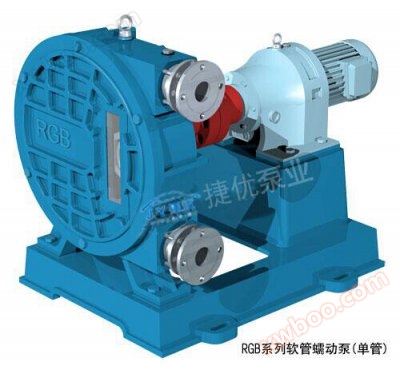
RGB series hose peristaltic pump
1、 Product Introduction and Working Principle: The RGB series hose pump (also known as peristaltic pump) works by squeezing the hose with a roller or
Product details
1、 Product Introduction and Working Principle
The RGB series hose pump (also known as peristaltic pump) works by squeezing the hose with rollers or sliders. Pumps can operate dry, self suction, and handle high viscosity and high wear media. The pump body does not need to be sealed, is completely leak free, and can output a fixed flow rate with each rotation. It has the characteristics of low speed and no noise, and is widely used in metallurgy, rare earth, desulfurization and environmental protection, water treatment, papermaking, painting, titanium dioxide, compound fertilizer and other industries. This series of pumps comes in two forms: single tube and double tube.
1.1 Working principle
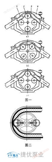
The working principle is shown in Figure 1, which consists of components such as hose 1, roller 2 mounted on rotor 3, and pump casing 4. When the rotor is rotated, the inner cavity A of the hose formed by the squeezing of the roller and the pump housing gradually increases from generation, and this cavity is in a suction state. When the rotor rotates to position b in Figure, the liquid that has entered chamber A is pushed by the roller to the enclosed cavity B. When it reaches position c in Figure, this part of the liquid is pushed back to chamber D, which is connected to the pump outlet, and then discharged outside the pump. The continuous rotation of the rotor forms a continuous "creep" of the hose, which continuously transports the liquid from the low-pressure inlet of the pump to the high-pressure outlet.
The number of rollers for squeezing the hose with a peristaltic pump can also be two, three, or more. On some pumps, the rollers are replaced by low friction compression elements with special front and rear edge shapes. Figure 2 is a schematic diagram of a peristaltic pump structure using two pulleys instead of rollers.
1.2 Main characteristics of the pump
a. Strong self-priming ability, with a water suction range of up to 8m;
b. Unique structure, no sealing is used, so there will be no leakage;
c. Can transport corrosive slurries, sludge, etc. containing a large amount of particles, fibers, or other impurities;
d. Low medium flow rate and no shear force, especially suitable for conveying materials sensitive to shear force;
e. Can transport high viscosity media, as well as three-phase mixed media of gas, liquid, and solid;
f. By adjusting the speed of the pump, the flow rate can be adjusted while the outlet pressure of the pump remains basically unchanged;
g. When the speed is constant, adjusting the outlet valve can change the outlet pressure of the pump, while the flow rate remains basically unchanged. Therefore, this pump has a certain metering function and can be used as a metering pump;
h. By using different hose materials, it can be adapted to different media. (Please request the corrosion parameter table of the hose from our company)
1.3 Wide range of applications
This pump is particularly suitable for corrosive media with high solid content and viscosity, and has superior self-priming performance. It is widely used in industries such as smelting (gold, silver, copper, lead, zinc, tin, nickel, cobalt, manganese), phosphate compound fertilizers, titanium dioxide, citric acid, rare earths, rare metals, inorganic salts, desulfurization and environmental protection, water treatment, papermaking, painting, etc. The specific applications are as follows:
a. Transportation of drilling mud and organic solvents such as crude oil, gasoline, kerosene, and fuel oil in the petroleum industry;
b. Acid, alkali, salt, phosphoric acid slurry, titanium dioxide slurry, and calcium citrate in the chemical industry; Crystallization liquid, suspension liquid, latex, resin, soft mud, and various material liquids;
c. Slurry transportation and rare metal liquid transportation in the smelting industry;
d. Drug delivery in the pharmaceutical industry;
e. Transportation of mud, lime slurry, and impurities in the water treatment and desulfurization industry;
f. Transportation of cement mortar in the construction industry;
g. Material transportation in the food industry;
h. Pulp and sulfur pulp transportation in the papermaking industry;
i. The transportation of ceramic glaze slurry in the ceramic industry;
j. The transportation of materials with poor fluidity such as paint, coatings, latex, etc. in the paint industry;
k. Toothpaste, emulsion, shampoo, conditioner, face cream, facial oil, etc. in the cosmetics industry;
l. Yeast, diatomaceous earth, wine tanks, syrups, ingredients, concentrates, gas-liquid mixtures in the beer industry.
II Pump model description and selection considerations
2.1 Model Description
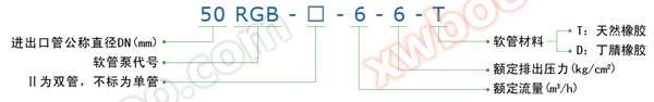
2.2 Selection considerations
When placing an order, please provide the following operating conditions: chemical composition of the medium, working temperature, solid content, actual usage pressure and flow rate, position and pressure of the suction fluid (positive or negative pressure), as well as the name and characteristics of the usage position, so that our company can select the most suitable model for you.
III Performance parameters of the pump
|
serial number
|
model
|
Rated flow rate(m3/h)
|
Rated discharge pressure(kg/cm2)
|
Rated speed(r/min)
|
Inner diameter of hose(mm)
|
Clear water suction distance(m)
|
Motor power(kw)
|
Allowable solid diameter(mm)
|
Maximum weight of the pump(kg)
|
drawing
|
|
1
|
32RGB-1-6
|
1
|
6
|
35
|
32
|
8
|
1.5
|
5
|
180
|
 1.rar 1.rar
|
|
2
|
40RGB-1.5-6
|
1.5
|
6
|
35
|
40
|
8
|
2.2
|
8
|
205
|
2.rar
|
|
3
|
50RGB-3.5-6
|
3.5
|
6
|
35
|
51
|
8
|
3
|
10
|
380
|
3.rar
|
|
4
|
50RGB-6-6
|
6
|
6
|
63
|
51
|
8
|
3
|
10
|
380
|
|
|
5
|
65RGB-8.5-6
|
8.5
|
6
|
35
|
64
|
8
|
7.5
|
12
|
645
|
4.rar
|
|
6
|
65RGB-13-6
|
13
|
6
|
63
|
64
|
8
|
7.5
|
12
|
645
|
|
|
7
|
65RGB-II-17-6
|
17
|
6
|
35
|
64
|
8
|
11
|
12
|
|
5.rar
|
|
8
|
65RGB-II-25-6
|
25
|
6
|
63
|
64
|
8
|
15
|
12
|
|
|
|
9
|
80RGB-13-6
|
13
|
6
|
35
|
76
|
8
|
11
|
15
|
1450
|
6.rar
|
|
10
|
80RGB-24-6
|
24
|
6
|
63
|
76
|
8
|
11
|
15
|
1450
|
|
|
11
|
80RGB-II-27-6
|
27
|
6
|
35
|
76
|
8
|
15
|
15
|
1520
|
7.rar
|
|
12
|
80RGB-II-48-6
|
48
|
6
|
63
|
76
|
8
|
18.5
|
15
|
1538
|
|
|
13
|
100RGB-25-6
|
25
|
6
|
35
|
102
|
8
|
15
|
15
|
|
8.rar
|
|
14
|
100RGB-45-6
|
45
|
6
|
63
|
102
|
8
|
18.5
|
15
|
|
|
|
15
|
100RGB-II-50-6
|
50
|
6
|
35
|
102
|
8
|
18.5
|
15
|
|
9.rar
|
|
16
|
100RGB-II-90-6
|
90
|
6
|
63
|
102
|
8
|
22
|
15
|
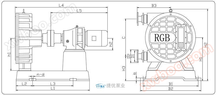
Five The appearance and installation dimensions of the pump
|
model
|
L1
|
L2
|
L3
|
L4
|
L5
|
h1
|
h2
|
H1
|
H2
|
H3
|
B1
|
B2
|
B3
|
C
|
b
|
D2
|
D1
|
n-d
|
drawing
|
|
32RGB
|
670
|
150
|
370
|
1000
|
563
|
280
|
150
|
380
|
648
|
220
|
280
|
340
|
365
|
320
|
24
|
140
|
100
|
4-Φ23
|
1.rar
|
|
40RGB
|
754
|
200
|
354
|
1025
|
588
|
280
|
150
|
385
|
648
|
365
|
280
|
330
|
365
|
320
|
24
|
150
|
110
|
4-Φ23
|
2.rar
|
|
50RGB
|
745
|
200
|
345
|
1368
|
1013
|
360
|
160
|
485
|
835
|
275
|
340
|
410
|
430
|
420
|
24
|
165
|
125
|
4-Φ23
|
3.rar
|
|
65RGB
|
860
|
225
|
410
|
1280
|
796
|
440
|
200
|
605
|
935
|
350
|
340
|
410
|
430
|
510
|
28
|
185
|
145
|
4-Φ23
|
4.rar
|
|
65RGB-II
|
1015
|
225
|
565
|
1576
|
1003
|
420
|
200
|
565
|
955
|
315
|
400
|
630
|
590
|
500
|
34
|
180
|
145
|
4-Φ24
|
5.rar
|
|
80RGB
|
1076
|
250
|
576
|
1595
|
1005
|
480
|
200
|
665
|
1100
|
340
|
480
|
540
|
710
|
650
|
34
|
195
|
160
|
4-Φ23
|
6.rar
|
|
80RGB-II
|
1250
|
250
|
750
|
1755
|
1067
|
480
|
240
|
635
|
1090
|
335
|
500
|
730
|
750
|
600
|
34
|
195
|
160
|
4-Φ24
|
7.rar
|
|
100RGB
|
1350
|
250
|
850
|
1898
|
1236
|
640
|
280
|
870
|
1485
|
430
|
540
|
1140
|
740
|
880
|
34
|
250
|
210
|
4-Φ26
|
8.rar
|
|
100RGB-II
|
1470
|
250
|
970
|
2007
|
1220
|
620
|
325
|
855
|
1458
|
485
|
960
|
1100
|
940
|
840
|
34
|
215
|
180
|
4-Φ26
|
9.rar
|
Note: 1. The flange size shall comply with GB/T9119-2000 and 1.0MPa; 2. If the installation size required by the user is different from the one in the table, please specify when ordering.
VI Handling, installation, use, and maintenance of pumps
6.1 Pump Handling and Installation
a. After receiving the equipment, the user should check whether the equipment, spare parts, random files, etc. are complete according to the packing list;
b. When transporting, use the lifting ring screws on the pump casing and the lower part of the motor as the focus points, and handle them gently without significant vibration or impact.
c. The pump should be installed in a spacious and easy to maintain area, with a flat foundation.
d. The inner diameter of the inlet and outlet pipelines of the pump should not be less than the specified requirements. For the convenience of maintenance, a valve can be installed in the outlet pipeline of the pump when using suction working condition; When using reverse flow conditions, valves can be installed in both the inlet and outlet pipelines of the pump, but all valves must be fully opened when the pump is in operation.
e. When the viscosity of the conveyed medium is high (>10000 centipoise), the inlet pipeline should be as short as possible and reverse flow conditions should be adopted.
f. When the pump is installed on a hard pipeline, it is best to load a hose of about 1.5m at the inlet and outlet of the pump to reduce pump pulsation and facilitate pump maintenance.
g. The weight of the inlet and outlet pipelines themselves cannot be directly borne by the inlet and outlet joints of the pump. Additional supports should be installed to prevent damage to the inlet and outlet joints.
h. As long as it is well coordinated with the direction of the motor, the inlet and outlet ends of the pump can be interchanged, and can be flexibly adjusted according to the needs during installation.
i. If the conveyed medium contains sharp or oversized solids, a filtering device should be installed at the inlet end of the pump.
6.2 Pump Operation
Before the pump starts working, please make the following preparations before starting up:
a. Check if the lubricating oil in the reducer inside the pump chamber is sufficient.
b. Check whether the inlet and outlet pipelines of the pump are installed and fixed properly, and whether the bolts at each flange are tightened.
c. Check if all inlet and outlet valves of the pump have been opened.
d. Press the start and stop buttons, jog the pump, check if the motor direction matches the inlet and outlet of the pump, and also check if the pump is stuck.
After the above checks are correct, the machine can be started for trial operation. When there are no abnormalities in all aspects, it can be put into normal operation.
6.3 Maintenance and upkeep of pumps
a. Regularly check the lubricating oil in the pump chamber and reducer. The lubricating oil in the pump chamber is usually replaced by replacing the hose (the lubricating oil in the pump chamber is glycerin). The reducer should be replaced regularly according to its instructions (lubricating oil is N46 mechanical oil).
b. After 15-20 days of continuous operation, the pump can remove the hose, rotate it 90 °, and then reinstall it, which can significantly extend the service life of the hose.
c. There should be no sharp or large solids in the conveyed medium, otherwise it will affect the service life of the hose.
d. Regularly check whether the connecting bolts and screws are loose.
e. Before the pump is stopped for a long time, it should be run idle for a few minutes to empty the medium in the hose, or necessary cleaning should be carried out with clean water.
f. When transporting media that are prone to crystallization, the medium in the hose should be emptied or cleaned with clean water before stopping the machine.
g. The coaxiality of the coupling should be checked regularly.
Special attention: 1 When this pump is in operation, all inlet and outlet valves should be opened, otherwise it may cause faults such as hose rupture and motor damage. If the conveyed medium generates hard sediment, it must be rinsed with clean water before shutdown, otherwise it may cause faults such as cracking of the impeller, coupling, and damage to the motor during the next startup!
7 Pump disassembly and assembly procedure instructions
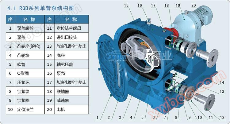
7.1 Disassembly Procedure for RGB Series Single Tube Pump (Refer to 4.1: Structural Diagram of Single Tube Pump)
a. After stopping the machine as required, remove the pipes at the inlet and outlet, run the pump by air for a few minutes, and empty the medium in the hose of the pump; Meanwhile, prepare a flat container to hold the lubricating oil inside the pump chamber.
b. Place the flat container under the oil drain hole, unscrew the oil drain hole bolt and pad (part 13), and drain the lubricating oil from the pump chamber.
c. When disassembling the parts at the inlet and outlet of the pump, first unscrew the nut (part 11) on the positioning flange (part 10), and then unscrew the inlet and outlet joint (part 12).
d. Then remove the positioning flange (part 10), locking ring (part 9), locking block (part 8), clamping ring (part 7), and O-ring (part 6) at once, so that the parts at the inlet and outlet ends are removed.
e. Unscrew the bolts (part 1) that secure the pump cover and remove the pump cover (part 2).
f. Tap the pump to rotate the cam seat (part 3) and cam block (part 4) to a horizontal position.
g. Unscrew the bolt on the pressure block of the fastening cam block (part 4) near one end of the pump inlet and outlet pipe, remove the pressure block and remove the cam block.
h. Tap the pump again to rotate the cam block on the other end 180 °, then unscrew the fastening screw on this cam seat, remove the pressure block, and remove this cam block.
i. Finally, use a lever to remove the hose, and if necessary, turn the pump to assist in removing the hose. This way, the entire pump head is completely disassembled.
j. Clean the pump chamber and other parts, replace hoses, and if necessary, replace other damaged parts. Pay special attention to checking whether the O-rings used for sealing are usable.
k. When assembling, assemble in reverse according to the above order. Attention: When installing the hose, the exposed parts of the hose at the inlet and outlet should be basically consistent. If necessary, first adjust the motor by rotating it forward, and then adjust it by rotating it in reverse until satisfactory.
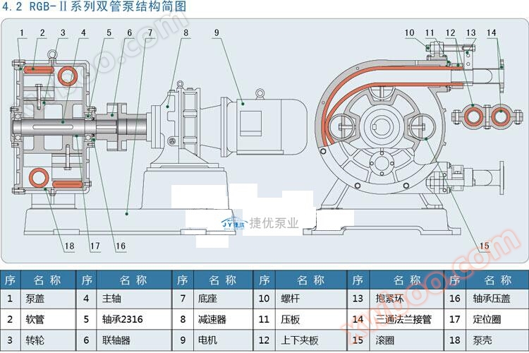
7.2 Disassembly Procedure for RGB-II Series Double Tube Pump (Refer to 4.2: Structural Diagram of Single Tube Pump)
a. After shutdown, remove the connecting pipes of the inlet and outlet, empty the medium in the hose, and prepare a flat container to release the glycerol in the pump chamber.
b. Loosen and remove the M12 bolt in the middle of the clamping ring (part 13), then remove the M20 bolt at the top, and remove the nut of the M36 screw (part 10).
c. Disassemble the bolts of the upper and lower clamping plates (part 12), remove the three-way flange connection (part 14) and the clamping ring.
d. Loosen the bolts of the O-ring pressure plate (part 11) and remove the pressure plate and O-ring.
e. Start the motor to rotate the hose (part 2) out of the pump casing (part 18).
f. Loosen the foot bolts connecting the reducer (part 8) to the base plate (part 7), remove the reducer and motor (part 9), and use a puller to remove the coupling (part 6).
g. Unscrew the bolts that secure the pump cover (part 1) and remove the pump cover and impeller (part 3) together.
Attention: When connecting the pump cover, impeller, and main shaft (part 4) together, pay attention to lifting when the weight is heavy; The bearing (part 5) on the coupling end is 2316 (or 2315), which can be pulled out together with the inner ring of the bearing.
h. Unscrew the bolts on the bearing end cover of the pump cover and remove the pump cover.
i. Remove the bearings or bearing inner rings at both ends of the main shaft, remove the locating rings (part 17) at both ends of the shaft, and knock out the main shaft from the wheel.
j. Loosen the bolt in the middle of the rolling ring (part 15), remove the pressure block, and sequentially remove the four rolling rings.
k. Clean other parts when replacing the hose, and replace them with new ones if any wear or damage is found.
7.3 Installation Procedure for RGB-II Series Double Tube Pump (Refer to 4.2: Structural Diagram of Single Tube Pump)
a. First, install the four rolling rings (part 15) on the wheel (part 3) with pressure blocks and bolts, and then install them in the middle of the main shaft (part 4). Place the fixing rings (part 17) on both ends, and then install the inner ring of bearing (part 5) 2316 (or 2315) on the coupling end, and install bearing 22316 (or 22315) on the other end.
b. The pump casing (part 18) should have a large mouth facing upwards. Install the outer ring of bearing 2316 at the bearing position, and install the bearing cover (part 16). Then, place the impeller into the inner cavity of the pump casing, fit the pump cover (part 1), and tighten the bolts, bearing cover, and oil seal.
c. Install the coupling (part 6) and rotate the main shaft smoothly without any jamming or noise.
d. Place the installed pump housing, reducer (part 8), and motor (part 9) together on the base (part 7), and tighten the foot bolts.
e. Connect the power supply, rotate the wheel, and insert the rubber hose (part 2) into the pump chamber, exposing both ends of the hose 8-10cm above the pump casing.
f. Insert one end of the three-way flange connection (part 14) and clamp the upper and lower clamps (part 12) securely.
g. Install another hose in the same way, put on the leak proof O-ring and pressure plate (part 11), then put on the clamping ring (part 13) of the three-way flange connecting pipe, insert it into the hose, install the upper and lower clamps and reinforce them with bolts.
h. Insert one end of the screw (part 10) into the clamping ring hole and fix it, then fix it on the pump casing with a large nut, paying attention to the gap between the upper and lower clamping plates and the pressure plate, so that it is aligned upwards.
i. Add glycerin (due to the corrosion and aging of rubber caused by engine oil) into the inner cavity of the pump casing until halfway through the lower sight glass.
8 Common faults and their troubleshooting methods
|
fault
|
Possible causes of malfunction
|
Methods for troubleshooting
|
|
no traffic
|
1. The valves in the inlet and outlet pipelines of the pump are not open;
2. The rotation direction of the pump is incorrect; 3. There is a large amount of air leakage in the suction pipeline; 4. Serious blockage in the suction pipeline; 5. The hose is severely damaged; 6. The viscosity of the medium is too high; 7. The suction stroke of the pump is too large. |
1. Open all valves;
2. Change the direction of the motor; 3. Identify the cause of gas leakage and eliminate it; 4. Remove blockages; 5. Replace the hose; 6. Thicken the suction pipe and adopt the reverse flow condition; 7. Increase the liquid level and reduce the suction stroke. |
|
The traffic is very small
|
1. There is a small amount of air leakage in the suction pipeline;
2. The suction pipeline is partially blocked; 3. The viscosity of the medium is relatively high; 4. The liquid level of the medium is very low, reaching the bottom of the pool; 5. The inner wall of the hose is severely worn. |
1. Identify the cause of gas leakage and eliminate it;
2. Remove blockages; 3. Thicken the suction pipe and adopt the reverse flow condition; 4. Stop the operation of the pump; 5. Replace the hose. |
|
Excessive noise
|
1. Parts are severely worn or damaged;
2. The medium contains a large amount of gas; 3. The outlet valve is opened too small or damaged; 4. The export pressure is too high. |
1. Check and replace parts;
2. Eliminate gas or continue working; 3. Fully open or replace the outlet valve; 4. Reduce the head of the device. |
|
Motor and reducer overheating
|
1. Excessive discharge pressure;
2. The viscosity of the medium is too high; 3. Severe wear and tear of parts; 4. Improper selection. |
1. Reduce the discharge pressure;
2. Reduce the viscosity of the medium or increase the motor power; 3. Replace parts; 4. Re select. |
Online inquiry
-
Contacts
-
Company
-
Telephone
-
Email
-
WeChat
-
Verification Code
-
Message Content
-