
VIP member

KGQ5F Feiteng Dual Power Series (three-stage)
Product Overview: This switch is suitable for dual power supply switches with 50/60Hz, rated voltage below AC690V, and rated current below 4000A. It c
Product details

scope of application
This switch is suitable for dual power supply switches with 50/60Hz, rated voltage below AC690V, and rated current below 4000A. It can achieve automatic or manual switching between the common power supply (N) and the backup power supply (R). The main and backup power sources can be the power grid, self starting generator level, battery, etc., and the main and backup power sources are determined by the user to enable unmanned operation of dual power customers. This switch is suitable for special or first level load users specified by the state, such as high-rise buildings, postal and telecommunications, coal mines and ships, industrial assembly lines, medical and health care, military facilities, airports, fire protection, metallurgy, chemical industry, textiles, petroleum and other important places that do not allow power outages.
Model and meaning

Note: 1. The standard configuration of the three-stage controller includes fire linkage (constant voltage DC24V, automatic power generation) function.
2. The two-stage standard does not come with fire protection or automatic power generation functions. If needed, separate notice must be given when placing an order.
product overview
Control device: LCD liquid crystal controller
Product structure: small size, high current, simple structure, ATS integration
Features: Fast switching speed, low failure rate, easy maintenance, reliable performance (with adjustable automatic switching time, 1s~99s)
Wiring method: Front board wiring (63, 125, 250, 630), rear board wiring (800, 1250, 2000, 2500, 3 200)
Conversion method: grid to grid, grid to generator, self switching and self restoring, self switching but not self restoring, mutual backup
Product shelves: 63, 125, 250, 630, 800, 1250, 2000, 2500, 3200, 4000
Product current: 20, 32, 40, 63, 80, 100, 125, 160, 200, 225, 250, 315, 350, 400, 500, 630, 800, 1000, 1250, 1600, 2000, 2500, 3 20 0, 4000 A
Product classification: Two segment without double disconnect position, three segment with middle double disconnect position
Number of product poles: 2, 3, 4
Product standard: GB/T14048.11
A TS level: PC level
operational condition
The ambient air temperature is -25 ℃~+40 ℃, and the average value over 24 hours does not exceed+35 ℃;
At a maximum temperature of+40 ℃, the relative temperature should not exceed 50%. At lower temperatures, a higher relative humidity is allowed, such as 90% at+20 ℃, but the possibility of condensation due to temperature changes should be considered;
The altitude of the installation site shall not exceed 2000m
◎ Category IV;
The inclination angle shall not exceed ± 23 °;
The pollution level is level 3;
If the above conditions cannot be met, the manufacturer should be consulted when ordering. This switch should be used for offshore, oil, and nuclear power plants
◎ Sign a separate technical agreement.

technical requirement
In automatic mode, when the common power supply is under voltage, over voltage, or under voltage, it switches to the backup power supply; When the backup power supply experiences the same fault, switch to the dual split position and the display screen will automatically sound an alarm;
◎ LCD screen protection for 30 seconds, the screen will be displayed when the button is pressed for the first time, and the settings can be entered for the second time. To enter the settings, a password is required;
When garbled characters (crashes) appear in manual settings, there is a reset button to reset to the default value;
When the controller is set to the automatic or manual position and the double split button on the controller panel is pressed, the display screen shows double split but does not sound an alarm;
The delay switching time set by the controller, when the power supply fails and returns to normal within the set value, does not switch between the dual power supplies, but switches instead.
Structural characteristics and functions
The KGQ5F type A · T · S, as the main dual power automatic switching switch, adopts electromagnetic drive and electrical mechanical interlocking mechanism. The main circuit contacts are static and dynamic structures, and the concave contacts are designed with a V-shape. To avoid long-term electrification of the magnetic coil, an electric circuit breaker is used, and mechanical maintenance is maintained. The control power supply is drawn from the main and backup current AC 220V (no additional control current is required). Due to its superior structural characteristics, the main and backup power sources will not be connected simultaneously, ensuring reliable operation and non-interference between the common and backup power sources. The switch has electrical or mechanical closing indication, and can also provide customers with normally open and normally closed passive protectionProvide assistance to customers for other purposes.
The intelligent controller provides multiple functions including overvoltage, phase failure control, undervoltage, delay control, generator control, fire reset, feedback signal, etc., and has strong anti-interference ability; It has three working modes: self restoration, self restoration without self restoration, and mutual backup; Equipped with common power supply and backup power supply; Common power supply and backup power supply combined; There are three stable working states for commonly used power sources and backup power sources; Easy to install, the control circuit adopts plug-in terminal connection; A dedicated handle can be used for manual conversion in manual mode.
Main technical parameters

Intelligent controller settings

Standard two-stage wiring diagram and working status

Standard three-stage wiring diagram and working status

Manual operation methods and precautions
Our company guarantees the switching performance of the electric operation of the product, but we cannot guarantee manual operation due to individual differences in the operator, opening and closing force, and speed. In artificial hands
There may be contact point consumption when operating the function of opening and closing or performing load opening and closing. If manual operation is required, please perform it in the following situations, and avoid manual operation in other situations.
When there is no operating power supply at all.
When inspecting the operating mechanism and contact parts.
When a malfunction occurs and the device cannot operate.
Note: When manually operating the power supply, it must be in the "OFF" state.
KGQ5F two-stage A and B power supply side input method

KGQ5F three-stage A and B power supply side input method

A Power Side Input Method

B Power Side Input Method
Switch body, external dimensions, installation dimensions
1 KGQ5F-16A~63A
2 KGQ5F-80A~125A

3 KGQ5F-160A~250A

4 APQ5F-315A~630A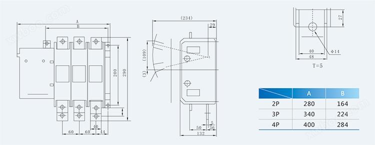
5 KGQ5F-800A~1600A
6 APQ5F-2000A~4000A

Online inquiry
-
Contacts
-
Company
-
Telephone
-
Email
-
WeChat
-
Verification Code
-
Message Content
-