
VIP member
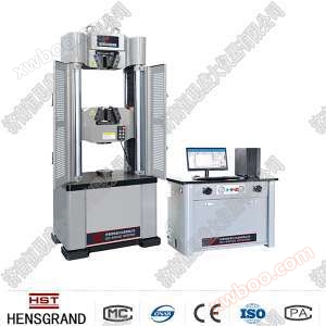
Introduction to the principle of hydraulic universal testing machine, what is the working principle of hydraulic universal testing machine
Hydraulic universal testing machine is a hydraulic material testing machine that can perform various tests such as tension, compression, bending, etc.
Product details
Hydraulic universal testing machine is a hydraulic material testing machine that can perform various tests such as tension, compression, bending, etc. Hydraulic universal testing machine is used for tensile, compression, bending and shear tests of various metal and non-metal materials, as well as special tests of some products. The test operation and data processing comply with GB228-2010 "Room Temperature Materials"

The requirements of standards such as "Metallic Tensile Testing Method". Hydraulic universal testing machines are generally composed of loading and measuring forces.
1、 Loading section
There are two fixed columns 2 and a fixed crossbeam 3 on the base 1 to form a load-bearing frame.

The working cylinder 4 is fixed on the frame. On the piston 5 of the working oil cylinder, a movable frame consisting of an upper crossbeam 6, a movable column 7, and a movable platform 8 is supported. When the oil pump 16 is started, the oil passes through the oil delivery valve 17, enters the working cylinder through the oil delivery pipe 18, and lifts the piston 5 together with the movable platform 8. In this way, if the specimen is installed between the upper chuck 9 and the lower chuck 12, due to the fixed lower chuck, the upper chuck will rise with the movable platform, and the specimen will be stretched. If the test piece is placed between two pressure bearing pads 11, or the bending test piece is placed on two bending supports 10, the movable platform will rise due to the fixed crossbeam not moving, and the test piece will be compressed or bent respectively. In addition, if you want to adjust the distance between the upper and lower clamps before the experiment starts, you can start motor 14 and drive screw 13 to raise or lower the lower clamp. But motor 14 cannot be used to apply tension to the specimen.
2、 Force measurement section
When loading, start the oil pump motor, open the oil delivery valve 17, the oil pump sends the oil into the working cylinder 4, and lifts the working piston 5 to load the specimen; At the same time, the oil flows through the return pipe 19 and the force measuring pipe 21 (this is because the return valve 20 is closed and the oil cannot flow back to the oil tank 37), enters the force measuring cylinder 22, and presses the force measuring piston 23, causing it to drive the rod 24 to move downward, thereby forcing the swing rod 26 and the swing hammer 25, together with the push rod 27, to rotate around the pivot point by 3. When the push rod deflects, it pushes the gear rod 28 to move horizontally, thereby driving the pointer gear of the force indicator disk 30, causing the force indicator pointer 29 to rotate around the center of the force indicator disk 30. The angle of rotation of the force indicator pointer is directly proportional to the total pressure of the force measuring cylinder (i.e. the tension acting on the tension rod 24). Because the oil pressure in the force measuring cylinder and the working cylinder is the same, the total pressure on the pistons of the two cylinders is proportional (to the ratio of piston area). In this way, the angle of the force indicator pointer is proportional to the total pressure on the working cylinder piston, that is, the load on the specimen. After calibration, the needle can directly indicate the size of the load on the force dial.
Online inquiry
-
Contacts
-
Company
-
Telephone
-
Email
-
WeChat
-
Verification Code
-
Message Content
-