
VIP member
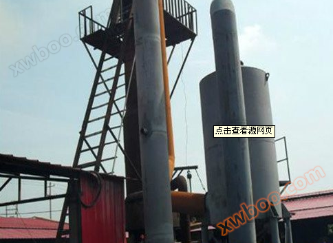
Design of Dust Removal System for Casting Workshop
Product Introduction: Introduction to Ventilation and Dust Removal Design in Casting Workshop: Dust Control in Casting Workshop, Design of Dust Remova
Product details
Ventilation and dust removal design for foundry workshop
Introduce dust control in the foundry workshop, design of dust removal system in the sand mixing machine department, and control of other major dust points in the foundry workshop
Controlling and managing dust during the casting process is an important measure to ensure safe production, labor protection, and prevent environmental pollution in enterprises.
Design of dust removal system for sand mixer
Before the technical transformation, the mixing process of this department, especially the addition of old sand, white mud in the powder, swelling, and the addition of coal powder during the mixing and rolling process, caused local dust concentrations to reach thousands of milligrams In order to enable the operator to see the grinding condition clearly on site, a fan was added to the standing position of the operator in the past to prevent dust from escaping towards the operator's side. This resulted in a larger dust source in the factory, causing large areas of dust to fly in the workshop, especially when a large amount of coal powder or graphite flew away, making it almost impossible to see clearly from a few steps away During the technical renovation of the sand processing department, it was decided to prioritize the treatment of this department to meet environmental protection requirements
This department is a front-line design and has installed four sand mixers, namely I-S1318, 2-Sl6, and I-S116A. Considering the author's habit of opening a closed door on one side to observe the sand mixing situation, the exhaust volume is set high at 3000m/h per unit, and the air duct design wind speed is calculated based on 18m/s for the dust removal system resistance According to relevant information, the dust removal system of the sand processing and mixing machine shows that when the air duct speed is between 18m/s and 19m/s, the length of the distant air duct is 30m/m, the number of exhaust points is 2h to 4h, and the estimated air duct resistance is 1kPa to 4kPa
The total resistance of dust removal includes three parts: the population resistance of the exhaust hood, the frictional resistance and local resistance of the air duct and its components, and the resistance of the purification equipment. The total resistance loss of the air duct is calculated by adding the resistance of each section of the air duct in a distant suction point or a loop with high resistance in the system The local resistance of frictional resistance can be determined based on the air volume and selected wind speed of each pipe section, and the pipe diameter can be determined according to relevant charts According to the calculation based on the following figure and the given conditions above, the total resistance loss of the air duct is about 1kPa, and the local resistance loss of the sealing enclosure is 150Pa. When using a bag filter, the working resistance is 1.1kPa-1.5kPa when the bag filtration wind speed is 2m-2.5m/min. The total resistance of this dust removal system is 100+l5+110-15-2.25kPa-2.65kPa. In addition, the calculated resistance loss difference between the parallel branches of the dust removal system should be less than 10%. When the resistance difference between the parallel branches of the dust removal system exceeds 10%, adjusting the pipe diameter, increasing the length of the air duct, and increasing the local resistance can be used to achieve balance
The total exhaust air volume of each section of the dust removal system should generally be considered based on the simultaneous operation of each exhaust point in that section. When some exhaust points work at different times and the exhaust air volume is large, the total exhaust air volume of each section of the air duct can be calculated based on the exhaust points that work simultaneously in that section The dust removal system of this factory is arranged with four sand mixers. If four mixers work simultaneously, the bag filter should be selected to be ≥ 90m, and the fan should be ≥ 5 fans. Considering that this department generally does not work simultaneously, with three mixers working simultaneously, a 75m bag filter and a 5A fan are selected for design and calculation based on this state The motor is selected as JO25l-2,13kW. At this time, the air flow range is 7950m/h-4720m/h, and the air pressure is 3.24kPa-2.24kPa. The total air flow required for the system is 9000in/h. Even if 15% -20% of the non simultaneous working exhaust air flow and 5% -10% of the bag filter and air flow are added, the air flow requirements can still be met. Butterfly valves are installed on the branch pipes of each intermittent exhaust point to adjust the closing of the intermittent equipment exhaust outlet when the equipment is not working at the same time The dust suction port of the sand mixer in the factory is located near the top of the sealed cover. To prevent the powder from being sucked away by a large exhaust volume, the sand mixing process is set to first add water and sand, and then connect the powder conveyed by the screw conveyor to the grinding wheel of the sand mixer through a bag connection Through the above measures, the dust removal effect of the system has reached the ideal state Choosing a bag filter in parallel and connecting multiple sand mixers in series for dust removal has its advantages and disadvantages compared to using a single insertion pulse bag filter. The former requires less one-time investment and is easy to install and maintain, but the disadvantage is that due to the large dust removal air volume, it will absorb a certain amount of powder and cause waste By adopting the above reasonable process methods and measures, the waste of powder can be reduced, which is relatively simple, feasible and economical
2. Dust removal system for sand treatment
The process of this section is complex, with a large amount of material transportation, multiple process equipment, and a large crossing area. Therefore, the hazards caused by dust points are also significant, making it a key focus of dust control in the casting workshop Therefore, in the technical transformation of combining mechanized material transportation, a 150m bag filter was designed and configured, with a fan of 4-72-U, 8C fan, and a motor of JO72-2.22kW. The air volume range of the facility is 17920m/h-31000m/h, and the air pressure is 2.52kPa-1.88kPa. The main air duct is 4680rain, which is further divided into upper and lower channels. The main air ducts of the upper air duct are 20IIlIII and 85ITlln, which are divided into two branches. The main pipe of one branch is a 00rain butterfly valve. When it is not necessary to pass through the linear vibrating screen, this valve is closed The main pipe of the other branch is 20mm, divided into five plow type unloaders. This main pipe adopts a tapered design, with a branch pipe at each tapered point, with a diameter of 4200rain. At the same time, it is equipped with a 4200rain butterfly valve to adjust and close the air flow loss at the unloading point when not in use The tapered pipe is 20-70-20-50-4200 (mm). The main air duct of the lower air duct is 4380mm, which is divided into two branches. One branch leads to the lower part of the elevator with a diameter of 50mm, and the other branch has a main pipe of 85mm leading to the sand storage hopper. The diameter of the air ducts at the two dust points of the sealed belt conveyor is 4200rain, equipped with 2-4200mm butterfly valves. When the belt is not running, the two butterfly valves are closed to adjust the air volume. This dust removal is ideal in application, which not only prevents dust from escaping, but also sucks out a large amount of ash in the old sand during the return process, thus improving the quality of the molding sand
3 Powder conveying dust removal
Powder conveying is a self-designed powder pressure conveying device that uses compressed air for pneumatic conveying to lift powder In this system, a built-in 7.5m bag dust collector is designed for the reversing and unloading areas. Compressed air is used to blow back and clean the dust in sequence, effectively controlling the dust generated during the material transportation process
4. Dust removal machine
The L128 inertia impact sand dropping machine is selected for the sand dropping machine. The traditional sand dropping method is to lift the sand by a crane without unhooking. As the sand dropping machine is located in the middle of the workshop, there is basically no lateral airflow, so a side suction hood is used for dust collection, which does not affect the process operation For this purpose, a 300m bag filter is selected, with a fan of 4-72-1l, a 10C fan, a motor of JO2-82-4, 40kW, an air flow range of 34800m/h to 50150m/h, and a wind pressure of 2.39kPa to 1.90kPa. The main suction duct is 00mm to the side suction hood, and is also divided into a branch to the lower part of the sand machine to the discharge and dust lifting point of the belt conveyor At the production site, the thermal updrafts and dusty water vapor generated by intense vibrations, impacts, air disturbances, and high-temperature castings are basically controlled
5. Clean the dust removal system of the work department
The current equipment of the cleaning department is one Qll8 cleaning drum, two ten headed+400mm grinding machines, and the dust removal system is designed with three headed grinding machines arranged The 90m bag filter is selected for the bag filter, and the fan is a 4-72 one liter, 5A fan. The motor is a JO2-5l-2.13kW motor, with an air volume of 7950m2/h-14720m/h and an air pressure of 3.24kPa-2.24kPa. Due to the large size of dust particles and the presence of a large amount of ground metal particles in the dust, this system adopts a two-stage dust removal, that is, an XLPII.5 cyclone inert dust collector is added before the bag filter The main suction duct of this system is 50rain and adopts a tapered pipe form, which is 1455-4325-4255-4200 (rain). The 1455rain variable diameter three-way splitter is divided into 20mm, and 4320rain is further divided into 4250rllln and 1.2oomill. The QH8 side suction hood is connected at 4250mill to control the dust escaping during the rolling operation of the drum, and the 4200mm variable diameter is connected to the vacuum cleaner carried by Qll8 itself The three-way branches to the dual head grinding machine are located at the tapered points of 25rain and 55rain, respectively. The diameter of the three-way branch is 4200rain, and it is further divided into 4, 13 or more branches to the enclosed dust hood of the grinding wheel. A 4200toni butterfly valve is added before the three-way branch to control and adjust the air flow This dust removal system is different from other dust collectors in that the air ducts are made of thicker iron plates
6 Primer Department Shot Blasting Equipment Dust Removal System
The dust removal system of the department is designed according to the layout of two Q3113A shot blasting drums and one Q378 single hook shot blasting cleaning machine, and also adopts the specifications and models of two-stage dust removal equipment
7 Chongtian Furnace Workshop Dust Removal
This department has achieved mechanization, automatic feeding, and dust points that escape when various furnace materials are discharged into the material bucket A LLH-20 vibrating bag filter is installed at this location to control the escape of dust The phenomenon of dust escaping from the top of the blast furnace causes significant pollution to the surrounding environment. Therefore, a new type of blast furnace dust removal cap has been designed Reduce the distance between the two layers of caps and the pipe body, and change the upper wind cap from the original large wind cap to a cap with the same diameter as the inner wind cap, so that the dust that is not blocked by the layer of caps is once again blocked from falling during the upward process by the peripheral side before the diameter change outlet of the second layer of caps. At the same time, increase the downward slope to allow the captured dust to fall smoothly From the scene, there is basically no escaping dust around, and the effect is quite ideal
Dust removal in the 8-core manufacturing department
The main dust point in the core making department is when bonding the two halves of the core heads. In order to achieve the requirement of parallel bonding, the bonding surface of the core heads needs to be ground flat after drying to facilitate bonding. Therefore, a uJH-15 vibrating bag filter is installed at the core grinding machine to control the escape of dust
9. Wood type workshop dust removal system
The mechanical equipment of this department is concentrated on one side of the factory building. The equipment currently has two wooden lathes, one cutting saw, one circular saw, one pressure planer, and one large and small flat planer The dust removal system design adopts an XM-6 woodworking cyclone dust collector The supporting fan adopts a dust exhaust centrifugal fan and a 10kW motor. The fan is placed in front of it to discharge the sucked wood dust into the cyclone dust collector and then into the enclosed cabin The vacuum suction pipeline is divided into two branches using a collection pipe form and further divided into multiple small suction ports. The suction ports are connected to various equipment dust points with snake skin hoses to control the escape of dust
The dust control in the casting workshop of the factory mainly focuses on these nine areas for treatment. For other dust such as dust before dry molding and smoke generated during casting, due to the inability to locate them, strengthened civilized production management is adopted to reduce the escape of dust After the governance, the testing data from the municipal environmental protection department is as follows: (unit: ms/m) large shaped section 3.0; Central design 1.8; Northern Small Item 1.6; Hybrid Machine 1.4; Cupola 1.5; Core 2.0; Clean shovel 1.5; Grinding wheel machine 2.0; Shot blasting drum 1.5. Except for the use of dry molding and the process of repairing and sealing the box after drying, which results in excessive dust escape, most of the large shapes have met the national standard range
The control and governance of dust pollution should start with process reform, realizing mechanization, automation, sealing, and equipped with certain ventilation and dust removal facilities, which is an effective way In the process of combining the technological transformation of the casting workshop, the factory has simultaneously solved the dust pollution in the casting workshop through self-designed segmented implementation, while proposing the mechanization of casting Especially with the dust control of the sand processing department, the ash content in the old sand can be effectively discharged, killing two birds with one stone and improving the product quality accordingly At the same time, the safety production and labor protection quality of the enterprise have also been guaranteed However, relatively speaking, the one-time investment in dust control is relatively large, the economic return rate is not significant, and the equipment maintenance investment after application also increases. In the face of the market economy environment, environmental awareness and legal education should be strengthened to raise this awareness uniformly. Otherwise, even if the environmental protection project is launched, if it is not timely invested in maintenance, it will become waste and cannot play its due role. This should be highly valued
Online inquiry
-
Contacts
-
Company
-
Telephone
-
Email
-
WeChat
-
Verification Code
-
Message Content
-