
VIP member
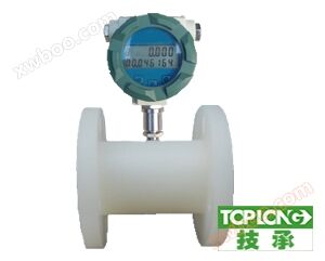
Corrosion resistant turbine flowmeter
Introduction: The LWGY-JC series corrosion-resistant turbine flow sensor (hereinafter referred to as the sensor) is a precision flow measurement instr
Product details
LWGY corrosion-resistant turbine flowmeter product description
The LWGY-JC series corrosion-resistant turbine flow sensor (hereinafter referred to as the sensor) is a precision flow measurement instrument, based on the principle of torque balance, and belongs to the velocity type flow instrument. Sensors have the characteristics of simple structure, lightweight, high accuracy, good reproducibility, sensitive response, and easy installation, maintenance, and use. They are widely used in industries such as petroleum, chemical, metallurgical, scientific research, water supply, and papermaking, and are ideal instruments for flow measurement and energy conservation.
Sensors and display instruments are used in conjunction, suitable for measuring liquids in closed pipelines that do not corrode stainless steel 1Cr18Ni9Ti, 2Cr13, corundum Al2O3, hard alloys, and have no impurities such as fibers or particles. If matched with display instruments with special functions, quantitative control, over limit alarm, etc. can also be performed. The explosion-proof type (ExmIIT6) of this product can be used in environments with explosive hazards.
The sensor is suitable for media with viscosity less than 5 × 10⁻⁶m2/s at operating temperature. For liquids with viscosity greater than 5 × 10⁻⁶m2/s, the sensor needs to be calibrated with real liquid before use.
LWGY corrosion-resistant turbine flowmeter product features
High precision options include 0.2%, 0.5%, and 1.0% precision.
Excellent repeatability
Equipped with 10 non-linear correction functions
Rich self diagnostic design, easy maintenance and disassembly
Multiple installation methods, suitable for different pipelines
Wear resistant hard alloy bearings, suitable for measuring corrosion resistance in closed pipelines with stainless steel 1Cr18Ni9Ti, 2Cr13, corundum Al2O3, and hard alloys
Corrosion resistance is suitable for corrosive media such as seawater, ammonia water, and acetic acid.
Paired with display instruments with special functions, it can also perform quantitative control, over limit alarm, etc.
Explosion proof type (ExmIIT6), can be used in environments with explosive hazards.
Bidirectional turbine flow meters are available for selection. Suitable for measuring the inflow and outflow of oil depots.
Multiple output pulses, 4-20mADC, on-site display, remote transmission display.
The power range is wide from 5 to 24VDC
Explosion proof grade ExdllCT6
Series diameter: 2, 4, 6, 10, 15, 25, 40, 50, 80, 100, 150, 200, 250, 300 mm.
LCD screen can have backlight display.
The integrated header can be equipped with RS 485 communication.
The integrated header can be equipped with upper and lower limit alarm and equivalent output functions.
Structure and working principle of LWGY corrosion-resistant turbine flowmeter
The sensor is a hard alloy bearing thrust type, which not only ensures accuracy and improves wear resistance, but also has the characteristics of simple structure, firmness, and easy disassembly and assembly. It mainly consists of a shell, a front guide frame, an impeller, a rear guide frame, a clamping ring, and a magneto electric induction converter with an amplifier.
Working principle of LWGY corrosion-resistant turbine flowmeter
When the measured fluid flows through the sensor, the impeller inside the sensor rotates with the help of the kinetic energy of the fluid. The impeller periodically changes the magnetoresistance in the magneto electric induction system, causing the magnetic flux passing through the coil to periodically change and generate an electric pulse signal. After amplification by an amplifier, it is transmitted to the corresponding flow integrator for measuring the flow rate or total amount. The fluid flows through the sensor housing. Due to the angle between the blades of the impeller and the flow direction, the fluid impulse makes the blades have a rotational torque. After overcoming the frictional torque and fluid resistance, the blades rotate. After the torque is balanced, the speed is stable. Under certain conditions, the speed is proportional to the flow rate. Due to the magnetic conductivity of the blades, it is in the magnetic field of the signal detector (composed of permanent magnet and coil). In the middle, rotating blades cut magnetic field lines, Periodically changing the magnetic flux of the coil, an electrical pulse signal is induced at both ends of the coil. This signal is amplified and shaped by an amplifier to form a continuous rectangular pulse wave with a certain amplitude, which can be transmitted to a display instrument to display the instantaneous flow rate or total amount of fluid. Within a certain flow range, the pulse frequency f is proportional to the instantaneous flow rate Q of the fluid flowing through the sensor, and the flow equation is:

F - Pulse frequency [Hz]
K - the instrument coefficient of the sensor [1/m3], given by the calibration sheet. If [1/L] is used as the unit
Q - Instantaneous flow rate of fluid (under working conditions) [m3/h]
performance parameters
| Accuracy: | 0.2 level (customized), 0.5 level, 1 level |
|---|---|
| Medium temperature: | -20-+120℃ |
| Ambient temperature | -20-+55℃ |
| Power supply: | Voltage: 24VDC, 220AC, lithium battery power supply |
| Transmission distance: | The distance from the sensor to the display instrument can reach 1000m |
| Protection level: | IP65/IP68 |
| Shell material: | The LCD display is made of low copper die cast aluminum, 304 stainless steel/316L stainless steel |
| Materials in contact with liquid: | 304 stainless steel/316L stainless steel |
| Pipe diameter: | DN4-DN350 |
| Communication protocol: | RS485 communication (MODBUS protocol) |
| Output: | 4-20mA current output, pulse output, with high and low alarm output |
| pipe diameter | DN4-DN350 |
Installation, use, and adjustment
(1) Installation
The installation method of sensors varies depending on the specifications, using threaded or flange connections. The installation methods are shown in Figure 1, Figure 2, and Figure 3, and the installation dimensions are shown in Table 2.

Whole table structure diagram

1. Compression ring 2. Bolt 4 × 14 3. Gasket 4. Sealing gasket 5. Steel wire 1Cr18Ni9Ti-0.8 × 2.5 6. Filter screen 7. Seat
Filter structure diagram
Figure 1 Schematic diagram of LWGY-4-10 sensor structure and installation dimensions

1. Shell 2. Front guide piece 3. Impeller 4. Rear guide piece 5. Pre amplifier
Figure 2 Schematic diagram of LWGY-15-40 sensor structure and installation dimensions

1. Ball bearing 2. Front guide component 3. Expansion ring 4. Shell 5. Pre amplifier 6. Impeller 7. Bearing 8. Shaft
Figure 3 Schematic diagram of LWGY-50-200 sensor structure and installation dimensions

Figure 4 Schematic diagram of sensor and display instrument wiring
technical performance
| Nominal diameter (mm) | L(mm) | H(mm) | G | L(mm) | D(mm) | d(mm) | number of holes | |
|---|---|---|---|---|---|---|---|---|
| LWGY-4 | 4 | 275 | 145 | G1/2 | 215 | |||
| LWGY-6 | 6 | 275 | 145 | G1/2 | 215 | |||
| LWGY-10 | 10 | 455 | 165 | G1/2 | 350 | |||
| LWGY-15 | 15 | 75 | 173 | G1 | ||||
| LWGY-25 | 25 | 100 | 180 | G5/4 | ||||
| LWGY-40 | 40 | 140 | 178 | G2 | ||||
| LWGY-50 | 50 | 150 | 252 | Φ125 | Φ18 | 4 | ||
| LWGY-80 | 80 | 200 | 287 | Φ160 | Φ18 | 8 | ||
| LWGY-100 | 100 | 220 | 322 | Φ180 | Φ18 | 8 | ||
| LWGY-150 | 150 | 300 | 367 | Φ250 | Φ25 | 8 |
Sensors can be installed horizontally or vertically, and the fluid direction must be upward when installed vertically. The liquid should fill the pipeline without any bubbles. During installation, the direction of liquid flow should be consistent with the direction indicated by the arrow on the sensor housing. The upstream end of the sensor should have a straight pipe section at least 20 times the nominal diameter length, and the downstream end should have a straight pipe section at least 5 times the nominal diameter. The inner wall should be smooth and clean, without defects such as dents, scale, and peeling. The axis of the sensor's pipeline should be aligned with the axis of the adjacent pipeline, and the gasket used for connecting and sealing should not penetrate deep into the interior of the pipeline.
Sensors should be kept away from external electric and magnetic fields, and effective shielding measures should be taken if necessary to avoid external interference.
In order to avoid affecting the normal transportation of liquids during maintenance, it is recommended to install a bypass pipeline at the installation location of the sensor.
When installing sensors outdoors, please ensure that the amplifier and plug are waterproofed. The wiring between the sensor and the display instrument is shown in Figure 4.
When there are impurities in the fluid, a filter should be installed, and the mesh size of the filter should be determined according to the flow rate of impurities, generally ranging from 20 to 60 mesh. When there is free gas mixed in the fluid, a deaerator should be installed. The entire pipeline system should be well sealed.
Users should fully understand the corrosion situation of the tested medium and strictly prevent the sensor from being corroded.
(2) Usage and adjustment
When using, the tested liquid should be kept clean and free of impurities such as fibers and particles.
When starting to use the sensor, it should be slowly filled with liquid before opening the outlet valve. It is strictly prohibited for the sensor to be impacted by high-speed fluid when it is in a liquid free state.
The maintenance cycle of sensors is generally six months. During maintenance and cleaning, please be careful not to damage the parts inside the measuring chamber, especially the impeller. Please pay attention to the position relationship between the guide components and the impeller during assembly.
When the sensor is not in use, the internal liquid should be cleaned and protective covers should be added at both ends of the sensor to prevent dust and dirt from entering, and then stored in a dry place.
The filter used should be cleaned regularly. When not in use, the liquid inside should be cleaned. Like the sensor, it should be added with a dust boot and stored in a dry place.
The transmission cable of the sensor can be laid overhead or buried underground (iron pipes should be covered when buried underground)
Before installing the sensor, connect the wires to the display instrument or oscilloscope, turn on the power, blow or manually turn the impeller to quickly rotate and observe if there is any display. When there is a display, install the sensor. If there is no display, check the relevant parts and eliminate the fault.
LWGYA corrosion-resistant turbine flow transmitter

The LWGYA corrosion-resistant turbine flow sensor adds 24VDC power supply and 4-20mA two-wire current transmission function on the basis of the LWGY basic turbine flow sensor, making it particularly suitable for use with display instruments, industrial control computers, DCS and other computer control systems.
Please refer to Part 2 of this manual, "LWGY Basic Turbine Flow Sensor," for the flow measurement range of each caliber of this transmitter, sensor structure dimensions, installation methods, maintenance, and other related information.
Flow calculation formula:
In the formula: Q - actual flow rate, m3/h
QF - upper limit value for flow measurement, m3/h, See Table 1
I - Current output, mA
Transmitter power supply voltage: 24V, (12V-30V)
Relationship between power supply voltage and load resistance:
In the formula: RLMAX - maximum load resistance, Ω
U - Supply voltage, V
Transmitter wiring: (+) -24V+B (-) -0V
LWGYA corrosion-resistant turbine flow sensor

The LWGYB on-site display turbine sensor is based on the LWGY basic corrosion-resistant turbine flow sensor and uses battery power to add on-site display function. This flowmeter is a new type of flow measurement instrument that integrates sensors and display calculations, developed using advanced ultra-low power single-chip microcomputer technology. Compared with the traditional measurement system composed of turbine flow sensors and secondary instruments, it has obvious advantages such as small size, light weight, intuitive and clear display readings, high reliability, no influence from external power sources, lightning resistance, and low overall cost. It can be widely used for liquid flow measurement in industries such as petroleum, chemical, light industry, and food. This product has superior performance and has reached the advanced level of similar international products. For the flow measurement range of each caliber of this flowmeter, sensor structure dimensions, installation methods, maintenance, etc., please refer to Part 2 of this manual, LWGY Basic Turbine Flow Sensor.
Selection code
| 1 | 2 | 3 | 4 | 5 | 6 | 7 | ||||||
| LWGY-JC- | - | - | - | - | - | - |
| type | |||||||||||||||||||
| LWGY | Basic type, powered by+5-24DCV, | ||||||||||||||||||
| LWGYA | 4-20mA two-wire current output, remote transmission type | ||||||||||||||||||
| LWGYB | Battery powered on-site display type | ||||||||||||||||||
| 1 | LWGYC | On site display/4~20mA two-wire current output | |||||||||||||||||
| Nominal Diameter | |||||||||||||||||||
| 4 | 4mm, Normal turbine flow range 0.04~0.25m3/h Wide range turbine with a capacity of 0.04~0.4m3/h |
||||||||||||||||||
| 6 | 6mm, Normal turbine flow range 0.1~0.6m3/h Wide range turbine is 0.06~0.6m3/h |
||||||||||||||||||
| 10 | 10mm, Normal turbine flow range 0.2~1.2m3/h Wide range turbine with a capacity of 0.15~1.5m3/h |
||||||||||||||||||
| 15 | 15mm, Normal turbine flow range 0.6~6m3/h Wide range turbine with a capacity of 0.4~8m3/h |
||||||||||||||||||
| 25 | 25mm, Normal turbine flow range 1-10m3/h Wide range turbine with a capacity of 0.5~10m3/h |
||||||||||||||||||
| 40 | 40mm, Normal turbine flow range 2-20m3/h Wide range turbine with a capacity of 1-20m3/h |
||||||||||||||||||
| 50 | 50mm, Normal turbine flow range 4~40m3/h Wide range turbine with a capacity of 2~40m3/h |
||||||||||||||||||
| 80 | 80mm, Normal turbine flow range 10-100m3/h Wide range turbine with a capacity of 5-100m3/h |
||||||||||||||||||
| 100 | 100mm, Normal turbine flow range 20~200m3/h Wide range turbine with a capacity of 10-200m3/h |
||||||||||||||||||
| 150 | 150mm, Normal turbine flow range 30~300m3/h Wide range turbine with a capacity of 15~300m3/h |
||||||||||||||||||
| 2 | 200 | 200mm, Normal turbine flow range 80~800m3/h Wide range turbine with a capacity of 40-800m3/h |
|||||||||||||||||
| explosion-proof | |||||||||||||||||||
| A | Unmarked, non explosion proof type | ||||||||||||||||||
| 3 | B | Explosion-proof type | |||||||||||||||||
| accuracy class | |||||||||||||||||||
| A | Accuracy class 0.5 | ||||||||||||||||||
| 4 | B | Accuracy level 1 | |||||||||||||||||
| Turbine type | |||||||||||||||||||
| A | Wide range turbine | ||||||||||||||||||
| 5 | B | Ordinary turbine | |||||||||||||||||
DN 4-DN40 caliber sensors are threaded connections, with a maximum working pressure of 6.3 Mpa;
DN50-DN200 caliber sensors are flange connected, with a maximum working pressure of 2.5Mpa;
Sensors with diameters ranging from DN 4 to DN10 are equipped with front and rear straight pipe sections and filters.
(2) Medium temperature: -20 to+120 ℃
(3) Environmental temperature: -20 to+55 ℃
(4) Power supply: Voltage:+5-24VDC, Current: ≤ 10mA
(5) Transmission distance: The distance from the sensor to the display instrument can reach 1000m
Online inquiry
-
Contacts
-
Company
-
Telephone
-
Email
-
WeChat
-
Verification Code
-
Message Content
-