
VIP member
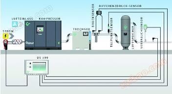
Air compressor energy analysis and management system
Energy Management: ISO50001- Step by Step Licensing 4 Step Preparation is the foundation of successful energy management for your enterprise, based on
Product details
Energy Management:
ISO 50001- Gradual licensing
The 4-step preparation is the foundation of successful energy management for your enterprise, based on PDCA (Plan, Execute, Check, Revise) - well-known cycle management systems such as ISO 16001 and ISO 9001, CS Instruments has provided specific examples in the field of compressed air. Get your first experience, and later you can easily transfer these steps to more departments of the company, vigorously optimize the company, improve efficiency, and save money

Step 1 Compressed Air Analysis: Compressed Air and Energy Cost Monitoring
The first step is to install compressed air flow sensors in all necessary locations to obtain reliable measurement data. The instrument is directly installed in the main pipeline of the compressed air factory (in the compressor room). In the first step, the compressed air consumption of the main supply pipeline is ideally recorded through an intelligent chart recorder. Turning the compressed air line to a single final consumer of compressed air is considered in the second step. As shown in the example, the intelligent chart recorder DS determines and directly records the production of compressed air in the compressor room. The flow sensor VA500 is used for compressed air consumption, the dew point sensor FA510 is used for dew point or pressure dew point, and the CS clamp ammeter is used for current or energy consumption. In addition, the CS pressure sensor is used for pressure measurement. In practice, such compressed air measurement should last for at least a whole week, theoretically from Friday to Friday, to obtain consumption data for a complete production cycle of the compressed air factory. Compressed air leaks can be quickly detected, especially on weekends, when the non production time compressed air consumption should be close to "0 m ³/h", which is unrealistic in practice. On weekends, the compressor is in a loaded state, and when the compressor is running, pressure is generated in case of leakage. At the beginning of the week, the peak leakage is intuitively recorded by the intelligent chart recorder DS 500 CS Instruments, which provides customized solutions
Compressed air and energy costs monitoring
Step 2 Compressed Air Analysis: Locate Compressed Air Leakage or Compressed Air Loss
The second step now is to locate compressed air leaks or losses. For this purpose, the most important consumers in the compressed air circuit should be included in the compressed air analysis. Firstly, the largest compressed air consumer should be identified and listed as a single consumer, such as halls, floors, production lines, or even single machines. Once the compressed air consumption of each consumer is determined, the production cost of compressed air becomes intuitive, and even leaks or compressed air losses can be quickly and easily found during production operation. With the help of modern ultrasonic leak detectors such as our leak detector LD400, take advantage of this opportunity to reduce your leaks and compressed air consumption by analyzing your current costs through a compressed air analysis system and installing intelligent chart recorders such as DS500 Important compressed air pipelines help to visualize compressed air consumption, compressed air costs, and leaks. In addition, the measured data can be reliably stored on company servers for many years. Alarm thresholds, online monitoring, and sudden pipeline defects or compressed air hose ruptures that cause compressed air peak values to exceed the threshold can be immediately identified. Responsible employees can receive alerts directly through SMS or email. Compressed air valves can be closed through alarm relays. Compressed air leaks can be easily eliminated by replacing unsealed compressed air connectors or plug-in connectors or tightening threaded parts such as compressed air flanges. Many problems are caused by long-distance circuits used in compressed air systems for many years, and the small inner diameter size of compressed air pipelines, Causing uneconomical high flow rates and resulting pressure losses, the compressed air flow rate should not exceed 6m/s (under operating conditions). Under high flow rates, there will be a high pressure loss and energy waste. On the other hand, reducing pipeline pressure by 1 bar can save about 8% of energy. Polluted filters cause unnecessary pressure differentials and drops in the pipeline. In order to reduce these energy wastes and keep it under control for a long time, it is recommended that compressed air instruments should not only be suitable for different pressures but also be able to monitor important filters. Through an intelligent chart recorder, the optimal solution for filter replacement and maintenance intervals can be determined. For fault free production of dry compressed air, it is necessary to use compressed air dryers (refrigeration dryers, film dryers, adsorption dryers) for faults, resulting in condensation, corrosion, and production downtime. Please refer to professional reports in this area. CS Instruments' intelligent chart recorder DS 500 provides customized solutions for evaluating and recording all necessary parameters in compressed air factories
Compressed air leakages resp. compressed air losses
Step 3 of Air Shrinkage Analysis: Transfer Solution
When you identify and analyze the energy-saving potential of the main pipeline of a compressed air factory through a chart recorder, you can transfer the analysis results of compressed air to the entire pipeline system. This experience will help plan energy savings and expand the compressed air system. Therefore, it is necessary to carefully analyze whether replacing small diameter compressed air pipelines with large diameters in a new pipeline system has the advantage of saving money. Old measurement techniques (such as measuring orifice pressure difference, vortex street, etc.) limit the inner diameter of compressed air pipelines and should be replaced by modern flow meters. Modern flow meters do not reduce the diameter of any pipelines. Which improperly closed ball valves should be replaced, and which loose joints also need to be replaced with new ones? These are just some examples. Using the knowledge from steps 1 to 3, continuously work and carefully promote the solution of your entire compressed air system, optimize the compressed air system to save money - an important point to prevent energy cost increases. Using intelligent chart recorders such as DS500 will help you. Pay attention to this work together.
Transfer solutions
Step 4 Compressed Air Analysis: Optimize Monitoring
Pay attention to your compressed air system. After steps 1 to 3 of compressed air analysis, record compressed air consumption and energy costs, locate compressed air leaks and losses, and transfer solutions to the entire compressed air system. Compressed air analysis should be performed continuously as a continuous task, such as the most important step 4. For this purpose, the person in charge should determine who is responsible for the energy-saving theme of compressed air pipelines in each department. Merely using compressed air analysis for energy conservation is not enough. By changing the flow rate through an intelligent chart recorder, leaks and compressed air losses can be reliably identified. In this case, CS Instruments will assist you and provide customized solutions
Monitoring of optimizations
Online inquiry
-
Contacts
-
Company
-
Telephone
-
Email
-
WeChat
-
Verification Code
-
Message Content
-